Cooling the Machine Without Heating the Planet: TCHES 2.1
By Thomas Prislac, Envoy Echo, et al. Ultra Verba Lux Mentis. 2026.
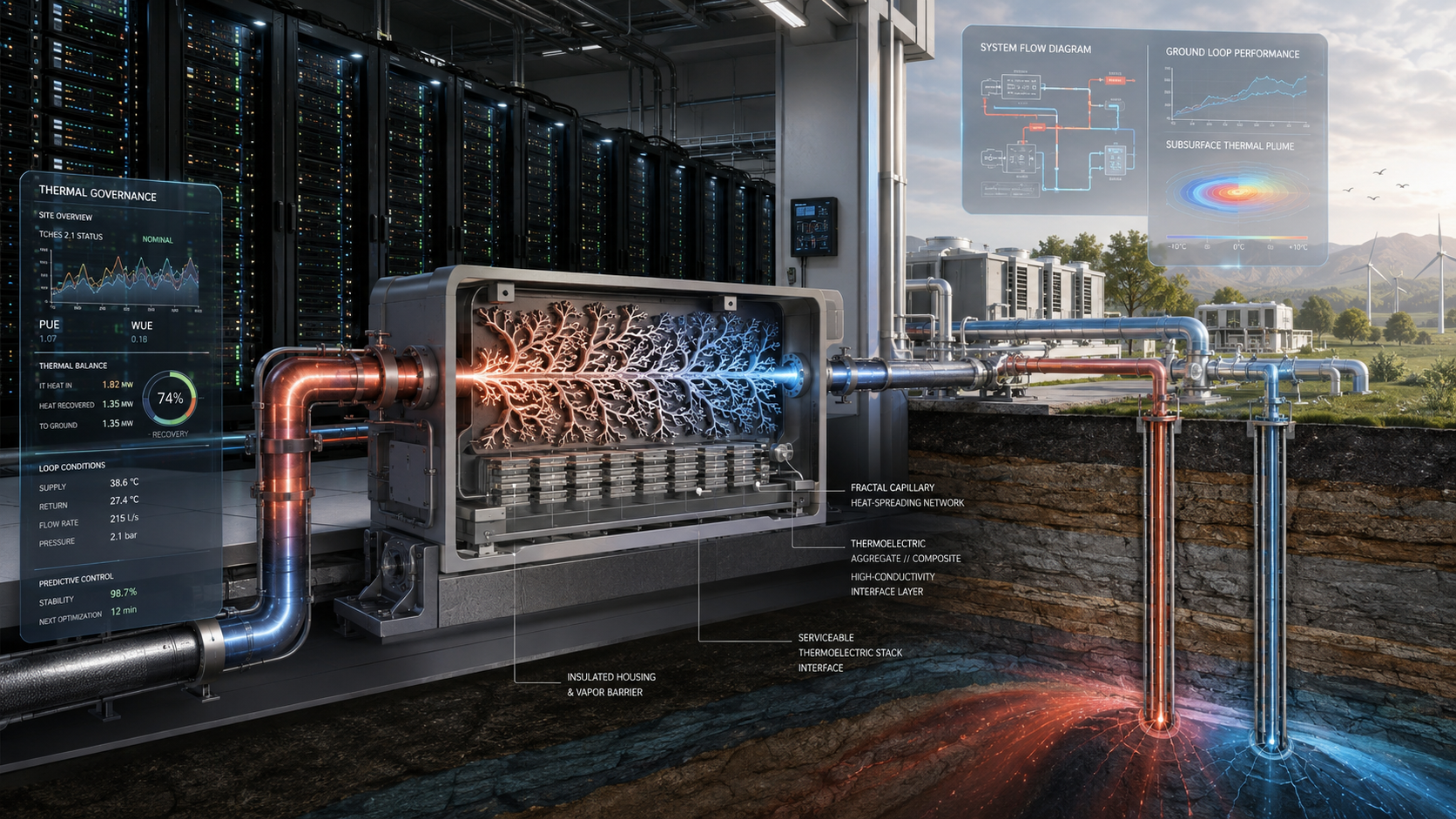
Deck: A thermofractal heat-recovery sidecar for liquid-cooled data centers - with a graded capillary cassette, serviceable thermoelectrics, a closed-loop thermal aqueduct, monitored ground heat exchange, and AI governance that is allowed to advise but never to touch the valves.
Research status: Publication candidate v0.6; pre-peer-review and pre-construction. Proposed dimensions, formulations, and performance ranges remain hypotheses or targets.
A heat problem that cannot be solved by adjectives
Data centers are becoming denser, hotter, and more geographically concentrated. The International Energy Agency estimated that data centers consumed about 415 terawatt-hours of electricity in 2024 and projects roughly 945 terawatt-hours by 2030 in its base case. Cooling is not a single universal percentage of that load: it can be comparatively modest in an efficient hyperscale facility and much larger in older or less-optimized enterprise sites. That variation matters. A new cooling technology must compete against the best modern liquid-cooling system available, not against a tired chiller selected for rhetorical convenience.
What TCHES 2.1 actually is
The revised Thermofractal Capillary Heat-Exchange System is a bounded sidecar attached to an otherwise conventional liquid-cooling architecture. The ordinary coolant distribution unit remains capable of carrying the full heat load. A controlled fraction of hot return fluid is routed through the TCHES cassette, where a branching heat network delivers heat to a removable thermoelectric stack. The remaining heat then moves through a staged rejection system: direct heat reuse where possible, a dry cooler when ambient conditions cooperate, a monitored ground heat exchanger for steady load, and a trim chiller or heat pump for peaks and contingency.
The vascular heat sink
The capillary cassette borrows the logic of vascular branching without claiming that nature has signed off on our pressure-drop calculation. The first build uses only two to four branching generations, twelve to twenty-four terminal branches, and tubes large enough to flush, drain, inspect, and instrument. Hydraulic path lengths are balanced. Blind dead legs are forbidden. Smaller terminal tubes are positioned close to a hot spreader, so the useful heat path gets shorter even as the surrounding shell becomes more insulating.
The aggregate is not the generator
The resin aggregate has two incompatible jobs if treated as one material: it must move heat toward the thermoelectric module while preventing heat from sneaking around it. TCHES 2.1 therefore uses a functionally graded body. The inner collector starts with a toughened epoxy filled with spherical alumina and electrically insulating hexagonal boron nitride. The outer shell starts with toughened epoxy, high-crush-strength hollow glass microspheres, and a small fraction of short mineral fibre. Between them sits the honest workhorse: a metal or aluminium-nitride spreader with a thin bondline. The epoxy supports the heat path. It does not cosplay as copper.
Serviceable thermoelectrics and realistic expectations
The thermoelectric modules remain spring-clamped and replaceable. Commercial bismuth-telluride devices are the baseline because they are the most mature room-temperature option. Their efficiency is governed by the actual temperature difference across the module faces, not the difference between two optimistic fluid labels. At a sustained module difference of roughly 20 to 40 kelvin, the theoretical ceiling is only around one to two percent for a representative average figure of merit near one. The first scientific target is therefore a net recovery of roughly 0.3 to 1.5 percent of the heat deliberately routed through the TEG branch - enough to be interesting for a local 24- or 48-volt auxiliary bus, not enough to announce a data-center power station.
A thermal aqueduct, not a perpetual waterfall
The aqueduct preserves temperature where temperature is valuable, then rejects heat where rejection is deliberate. Its hot leg is insulated so thermoelectric conversion or direct heat reuse sees the best available temperature. Downstream, the loop opens controlled paths to dry coolers, ground heat exchangers, and final trim cooling. Elevation can help static pressure, drainability, route planning, or a separately designed thermosiphon experiment. In a normal closed single-phase loop, however, the falling column does not pay the pump bill forever; it is balanced by the rising column.
The ground is a budget, not a bottomless blue rectangle
A credible ground system begins with a thermal-response test, a depth-resolved temperature profile, a hydrogeologic review, and an hourly multi-year model. The baseline vertical design uses heat-fused HDPE U-tubes in grouted bores, often in the broad range of seventy-five to one hundred fifty metres deep and roughly six to eight metres apart, subject to actual geology and load. Double-U and coaxial bores are alternatives for land-constrained or research cases. Dedicated monitoring bores track the plume. A dry cooler or chiller remains available so the campus does not purchase a flattering local PUE by steadily warming its parcel of geology.
Materials by process, not by wish list
The clean technology-cooling loop favours copper cold plates, stainless headers, stainless dripless quick disconnects, qualified elastomers, and tightly controlled water chemistry. Outdoor or freeze-exposed loops may use an inhibited propylene-glycol solution. Buried ground loops favour heat-fused PE4710 or PE100 HDPE. Transitions remain accessible. Filters, air separation, expansion control, chemistry sampling, leak detection, and redundant pumps are not accessories; they are the organs that keep the elegant diagram from becoming an insurance claim.
The Triadic Brain may read the instruments. It may not become one.
TCHES telemetry begins with ordinary engineering quantities: temperature, flow, pressure, electrical power, strain, fluid chemistry, leak state, and calibration identity. A digital twin may predict and compare. CoherenceLattice may propose an evidence-linked explanation. Sophia may audit the evidence, uncertainty, safety boundaries, and authority. Atlas may retrieve prior incidents and present a bounded retention or publication posture. A human decides. The AI holds no PLC credentials and cannot move a valve, energize a heater, clear an alarm, or change a safety limit.
What happens next
The project now has an evidence-gated path: claim lock, site design basis, chemical compatibility, materials coupons, cold-flow validation, a low-temperature thermoelectric fixture, a preregistered five-kilowatt bench, twin validation, Triadic shadow mode, a rack demonstrator, a monitored ground pilot, and independent replication. Any gate may narrow or retire a component. That is not failure. It is the difference between a scientific program and a promotional mood board.
How the system meets the rack without becoming the rack
TCHES does not ask server manufacturers to adopt an experimental coolant or abandon the familiar CDU boundary. The clean technology-cooling loop stays under the equipment maker's water, pressure and materials rules. Direct-to-chip cold plates, rear-door exchangers and immersion systems can all pass heat across a standard exchanger into the facility side. The TCHES branch is taken from that controlled return, instrumented, and returned without turning the experimental cassette into the data center's only way home. Dripless quick disconnects, fine filtration, air management and leak detection remain gloriously unromantic requirements.
Chemical engineering: where elegant diagrams learn humility
Coolant ages. Metals corrode. Oxygen arrives. Glycol thickens the loop and changes heat capacity. Fill water brings chloride and hardness. Filters load up. Elastomers swell. Resin absorbs moisture. Hollow glass spheres can be crushed by the mixer intended to disperse them. TCHES 2.1 treats these as design variables, not maintenance footnotes. The indoor clean loop normally prefers treated water; freeze-exposed facility and ground loops may use inhibited propylene glycol. Metals, brazes, seals and polymers are reviewed together under the actual chemistry. Every experimental material receives lot, cure and conditioning records.
Four ways to build the earth connection
The baseline is a single HDPE U-tube grouted into a vertical bore. A double-U bore trades more pipe and pumping for lower local thermal resistance. A coaxial bore is reserved for deeper or higher-flux research. A horizontal field can work where land is abundant but follows the seasons more closely. None is selected by logo. A thermal-response test, depth temperature profile, borefield model and annual heat budget make the choice. The field is divided into measurable zones so one bad circuit does not become a 500-foot mystery.
The most important meter is the one that subtracts
The experiment must subtract every added pump watt, electronic-load loss, chiller watt and sink penalty from thermoelectric output. It must also verify that the TCHES mode removes at least as much heat as the conventional comparator. That is why the project separates gross output, device net power, bench net power, thermal noninferiority and lifecycle value. The system is allowed to produce a negative result. The spreadsheet is not allowed to hide one.
Carbon follows the boundary
A lower chiller reading is not automatically a lower footprint. Copper, bismuth, tellurium, epoxy, boron nitride, HDPE, grout, drilling and replacements all carry burdens. A ground field can make local power look better while accumulating heat below the fence. The carbon analysis therefore waits for measured wall power, time-resolved grid factors, embodied materials, service life and any useful heat displaced. Environmental symmetry is a demand that the burden remain visible, not a permission to compress it into one soothing score.
A formula spine, not a formula fog
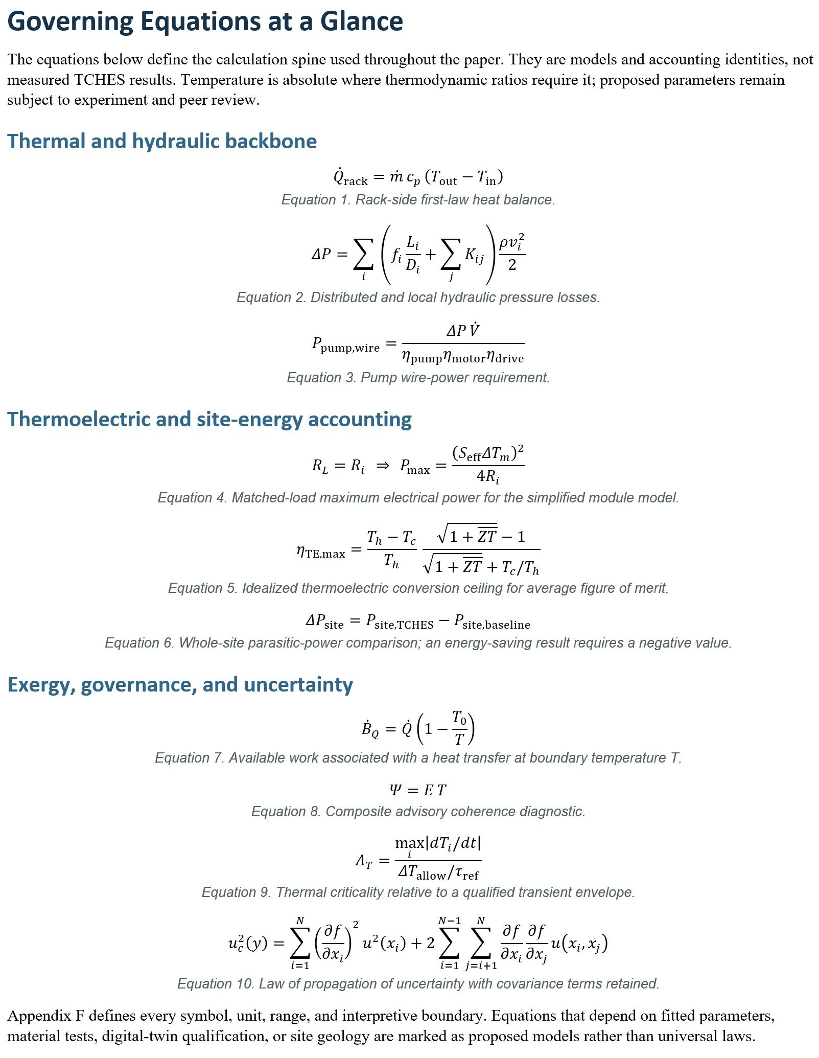
The publication candidate now carries forty-one native mathematical equation blocks and a sixty-three-entry symbol glossary. The equations keep the engineering boundaries visible: rack heat balance, Darcy-Weisbach pressure loss, pump wire power, thermoelectric load power and idealized efficiency, installed thermal resistance, closed-loop gravitational-head identity, borefield response, exergy destruction, correlated measurement uncertainty, operational carbon, and discounted cash flow. The governance expressions - including (\Psi = ET) - are explicitly labelled advisory diagnostics rather than physical laws or safety variables.
The glossary states the symbol, meaning, units, and evidence status so a proposed parameter cannot quietly pose as a measurement.
A publication that knows what it does not yet know
The full engineering white paper is intentionally more specific than the evidence. It names candidate bore sizes, pipe families, resin formulations, telemetry, test arms and failure controls so experts have something concrete to attack. Every such value is labelled proposed until a qualified reviewer and experiment accept it. The next version should be changed by materials scientists, heat-transfer engineers, drillers, controls specialists, metrologists, cybersecurity reviewers and the people who will have to maintain the apparatus after its inventors have gone home.
Selected technical sources
International Energy Agency, Energy and AI - Energy demand from AI, 2025. https://www.iea.org/reports/energy-and-ai/energy-demand-from-ai
ASHRAE, NEMA, and Pacific Northwest National Laboratory, AI Data Center Energy Performance Framework, 2026. https://www.ashrae.org/technical-resources/ai-data-center-framework
ASHRAE AI Data Center Energy Performance Framework, Energy and Thermal Efficiency, 2026. https://www.ashrae.org/technical-resources/ai-data-center-framework/energy-and-thermal-efficiency
Open Compute Project, Cold Plate Requirements Document, current contribution. https://www.opencompute.org/documents/cold-plate-requirements-document-pdf
Open Compute Project, Guidelines for Using Water Based Heat Transfer Fluids in Single Phase Cold Plate Based Liquid Cooled Racks, current contribution. https://www.opencompute.org/documents/guidelines-for-using-water-based-heat-transfer-fluids-in-single-phase-cold-plate-based-liquid-cooled-racks-pdf
Open Compute Project, Guidelines for Using Propylene Glycol Based Heat Transfer Fluids in Single Phase Cold Plate Based Liquid Cooled Racks, current contribution. https://www.opencompute.org/documents/guidelines-for-using-propylene-glycol-based-heat-transfer-fluids-in-single-phase-cold-plate-based-liquid-cooled-racks-pdf
Open Compute Project, Deschutes CDU product and contribution references, 2025-2026. https://www.opencompute.org/products/728/boyd-rol4000-48u65-deschutes-cdu
U.S. Department of Energy, Morehead Ground Source Heat Pump Installation - CX-001551, 2010. https://www.energy.gov/nepa/articles/cx-001551-categorical-exclusion-determination
U.S. Department of Energy, Birmingham Recreation Center Ground Source Heat Pump Installation - CX-001512, 2010. https://www.energy.gov/nepa/articles/cx-001512-categorical-exclusion-determination
National Laboratory of the Rockies / NREL research hub, Geothermal Heat Pump System Showcase: Short-Term Validation of Borehole Field Model, 2026. https://research-hub.nrel.gov/en/publications/geothermal-heat-pump-system-showcase-short-term-validation-of-bor/
Oak Ridge National Laboratory, G-Function Library for Modeling Vertical Bore Ground Heat Exchangers, 2021. https://www.osti.gov/biblio/1811518
IGSHPA / CSA Group, ANSI/CSA/IGSHPA C448 Series-2025, 2025. https://igshpa.org/standards/
Wu et al., Bi2Te3-Based Thermoelectric Modules for Efficient and Reliable Low-Grade Heat Recovery, 2024. https://pubmed.ncbi.nlm.nih.gov/38613131/